4.2. Using Objects
4.2.1. Adding Objects
Adding objects to the Dia canvas is done by clicking on the desired object's icon button in the Toolbox and then clicking on the canvas at the desired insertion point. The selected object will be inserted at that point.
![[Tip]](images/tip.png) | |
You can quickly add multiple objects of the same type to the diagram using the Space key to toggle between the Modify control and the desired object. For example, say you wish to add several Box objects to the diagram. First, click on the Box icon and click on the canvas to add the Box. At this point, the Modify control will be selected automatically. To reselect the Box control, press the Space key. Now you can click on the canvas again to add a second Box object. Continue to press Space and then click to add as many Box objects as desired. |
| |
If you are using different colors or line styles for different objects, one trick to save time is to create a separate file of sample objects with the desired properties on a separate diagram. Then copy and paste these objects onto your working diagram as you need them. |
4.2.2. Moving Objects
When an object is inserted into the canvas, the desired object will appear with small green boxes (known as handles) around the border.
Figure 4.12. Object Handles
To move an object,
click anywhere inside the object (or somewhere on a line other than
a handle) and drag the mouse to the desired location on the canvas. For
line objects, you need to click on the line.
| |
When moving an object, be sure not to click on a handle. Otherwise, you will resize the object instead of moving it. |
4.2.3. Resizing Objects
Handles are used to change the size of the object. To expand an object, just click a handle and drag it away from the center of the object. To shrink an object, drag a handle toward its center. The object's size will change as you drag the mouse. If an object has a fixed aspect ratio, changing one dimension automatically changes the other. If an object has a free aspect ratio, you can change one dimension (e.g., height) without affecting the other (e.g., width). Some objects have a property setting that determines whether the aspect ratio is fixed or free.
4.2.4. Deleting Objects
To delete an object, click on the object to select it. The handles will display, which indicates that the object is selected. Then press the Delete key or select → from the menu.
4.2.5. Connecting Objects With Lines
In many diagrams, shapes are connected to each other using one of the basic line objects. When a shape is not selected, a number of connection points are displayed on its borders as small "x" figures. There is also a connection point in the middle of each shape. Lines also have connection points where other lines can connect.
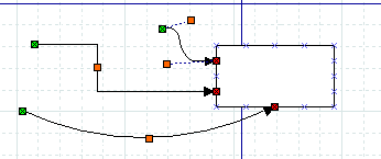
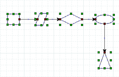
Lines have handles on each end that are used to connect them to other objects. These handles are green if the line is not connected and red if it is connected. Lines also have orange handles that are used to shape the line. The figure below shows several lines with green handles on the unconnected end and red handles on the connected end.
Figure 4.13. Line Handles
To connect two shapes with a line:
Select the desired line (Line, Zigzagline, etc.) by clicking on the Toolbox icon.
You can either click on the canvas to place the line on the diagram and then drag the "from" end of the line to the desired connection point of the first object.
Or you can save a step by clicking directly on the desired connection point of the first object. In this case, the line will display with the "from" end of the line already connected to the first object.
In either case, when the "from" end of the line is connected, it's "from" handle will be red.
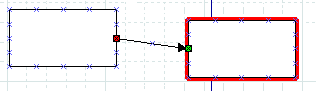
Click on green handle at the "to" end of the line and drag it to the desired connection point on the second object. When the line is connected, the outline of the object being connected will turn red, as shown in the figure below.
Figure 4.14. Line Connected
At this point, the two objects are connected. If you move either object, the line will stretch to keep them connected. If you move the line, it will disconnect from both objects. If you do this by mistake, you can undo using Ctrl+Z or → .
At any time, you can disconnect or connect to a new point by clicking on the "from" or "to" handle and dragging it to a new location on the diagram.
| |
If you connect a line to a fixed point on a shape's perimeter, it will stay connected to this point when the object is moved. Figure 4.15. Fixed Connection Point 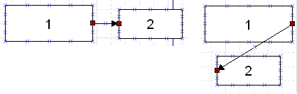
If you connect a line to the middle of an object, when you move the object the displayed connection point moves automatically, so you don't need to change the connection point. Figure 4.16. Middle Connection Point 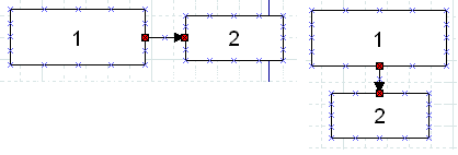
Note that, when a line is connected to the middle of an object, the line's connection handle is still positioned on the perimeter of the object. So to move the line's connection point, drag on the line's handle (as opposed to the middle of the object). |
| |
If you connect a Line or Polyline object to the middle of a shape when you first place the line on the canvas, you need to be careful when connecting the "to" end of the line. Be sure to click on the line's handle and not on the surrounding area within the shape. If you click on the surrounding area inside the shape, you will select the shape and not the line's handle. If this happens, click outside the shape to deselect it and then carefully click on the "x" in the middle of the object (not on the line's arrow). The handle will display, and you can drag it to the desired location. Note that the handle will display as red, because it is connected to the middle. Also note that you need to drag it outside the shape before you can see the line. |
See Basic Objects / Line for more information on the different lines available.
4.2.6. Entering Text
Text can be entered by selecting the object, entering text edit mode and then typing the text. The font, size, alignment, and other formatting properties can be changed by double-clicking the object, when not in text edit mode.
Many Dia objects suport in-canvas editing of text. Dia versions before 0.97 had not explicit distinction between a selected object and it's text edit mode. As a result numerous workarounds were needed to support canvas and text editing with the same set of keys, e.g. the Delete key was not deleting the character right to the cursor, but instead the whole object.
With Dia 0.97 and later there is a dedicated text edit mode. You can enter it by hitting Enter or F2 key while an appropriate object is selected. To leave text editing just click outside of the editable area or hit the Escape key.
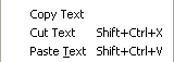
Figure 4.17. Edit Menu Text Commands
| |
While in text edit mode the normal Copy / Paste keys (Ctrl+C, Ctrl+V) work on the entire text. The Edit menu also contains the commands Copy Text, Cut Text (Shift+Ctrl+X), and Paste Text (Shift+Ctrl+V) to copy, cut, and paste just the text contents of an object. Note that when you paste text into an object, the text is formatted according to the Dia object properties, not the text source. |
| |
You cannot select a section of text inside an object with the mouse (this moves the cursor). You can insert characters at the current cursor position just by typing. You can delete the character to the left of the mouse using Backspace. The Del key deletes the character right to the cursor. To delete all of the text in an object, use the Cut (Shift+Ctrl+X). |
4.2.7. Aligning Objects
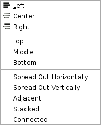
Dia provides several options to help arrange multiple objects without needing to move each object individually. These are available on the → menu choice shown below.
Figure 4.18. Objects / Align Options
4.2.7.1. How To Align Objects
To align objects, first select the objects to align (see Selecting Objects ) and then execute one of the align commands, using either the menu or the shortcut key. The order in which objects are selected does not matter.
4.2.7.2. Left, Center, and Right Align
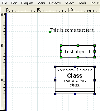
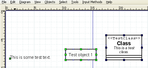
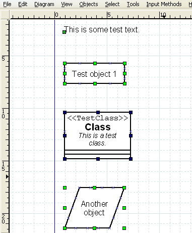
The align left, right, and center are used to align objects arranged vertically on the canvas. The align left aligns the selected objects to the left edge of the left-most object. Similarly, the align right aligns the selected objects to the right edge of the right-most object. Align center aligns the center of each object to the mid-point between the extreme left and extreme right edge of all selected objects. Examples of align left, center, and right are shown below.
Figure 4.19. Before Left, Center, Right Align
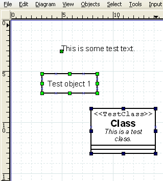
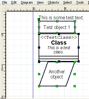
Figure 4.20. Align Left
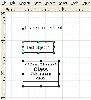
Figure 4.21. Align Center

Figure 4.22. Align Right
4.2.7.3. Top, Middle, and Bottom Align
The align top, middle, and bottom are used to align objects arranged horizontally on the canvas. The align top aligns the selected objects to the top edge of the upper-most object. Similarly, the align bottom aligns the selected objects to the bottom edge of the lowest object. Align middle aligns the middle of each object to the mid-point between the extreme top and extreme bottom edge of all selected objects. Examples of align top, middle, and bottom are shown below.
Figure 4.23. Before Top, Middle, Bottom Align
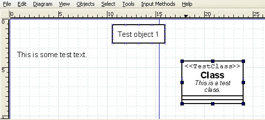
Figure 4.24. Align Top
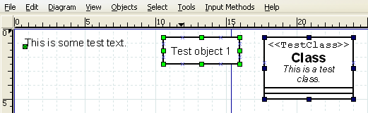
Figure 4.25. Align Middle
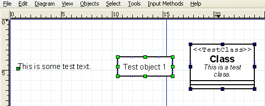
Figure 4.26. Align Bottom
4.2.7.4. Spread Out Horizontally and Vertically
The Align / Spread Out commands can be used to create uniform spacing for objects arranged either horizontally or vertically. Examples of these commands are shown below.
Figure 4.27. Before Spread Out Horizontally
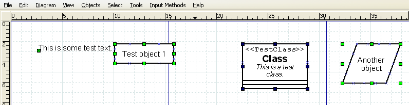
Figure 4.28. After Spread Out Horizontally
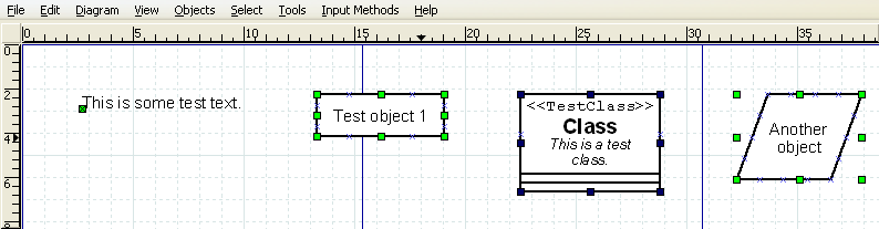
Figure 4.29. Before Spread Out Vertically
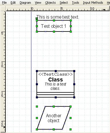
Figure 4.30. After Spread Out Vertically
4.2.7.5. Align Adjacent or Stacked
The Align / Adjacent command is used to place objects next to each other with no horizontal space in between. The Align / Stacked is used to place objects directly on top of each other, with no vertical space in between. Examples of these commands are shown below.
Figure 4.31. Align / Adjacent
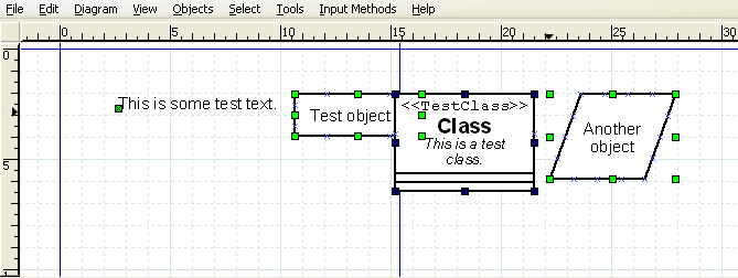
Figure 4.32. Align / Stacked
4.2.7.6. Align Connected
The Align Connected command tries to align connected objects, so that the connecting lines are either horizontal or vertical afterwards.
Figure 4.33. Before Align Connected
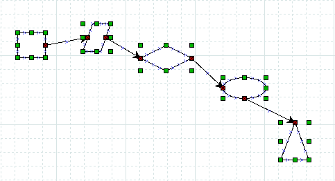
Figure 4.34. After Align Connected
![[Note]](images/note.png) | |
The algorithm used to align connected objects is not fool proof, infact it is very simple. If the resulting alignment does not match your expectations use Undo to revert it. A different selection of objects may producae a result more to your liking. |
4.2.8. Grouping Objects
Grouping allows you to treat several objects as a single entity. A group enables you to fix the position of the member objects in relation to each other and to change the properties of all member objects at one time. To create an object group, select two or more objects and then select → .
Figure 4.35. Before and After Group Create
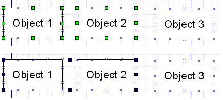
When the group is created or subsequently selected, a set of black handles displays around the outside of the group, as shown in the figure above. At this point, you can move the entire group just like you would move a single object. Just click and drag on any of the objects in the group.
You can also change the properties of all objects in a group by double-clicking or using the right-click context menu. See Changing Properties for a Group of Objects for more information.